JZ / REV.03
OPEN TO WORK
DRAWING NO.JZ-2026-001
SUBJECTJ. ZHAO
SCALE1 : 1
SHEET01 / 06
UNITSSI · IMP
TOL.±0.05
SUBJECT · NAMEPLATE JUSTIN ZHAO DRAWN BY: SELF · 林
MECHANICAL ENGINEERING · STUDENT
VEHICLE SYSTEMS  /  SUSPENSION  /  FORMULA SAE
01 /

ABOUT THE SUBJECT

Cal Poly Racing Formula SAE car 253, side view, showing the rear wing, sidepod and front suspension.
SUBJECTCPR CAR 253
VIEWSIDE ELEV.
SCALENTS
DWGJZ-A-001
FIG. 01 — CAL POLY RACING FSAE · CAR 253, SIDE VIEW

Mechanical Engineering junior at Cal Poly San Luis Obispo with extensive hands-on experience from Cal Poly Racing.

Third-year member and lead of the suspension team — responsible for designing, manufacturing, and assembling suspension components using a variety of machining tools.

Proven ability to take responsibility for real hardware, work in a fast-paced team environment, and apply engineering theory to practical vehicle performance.

  • A
    DETAIL · OWNERSHIP Real hardware. Real consequences.
  • B
    DETAIL · WORKFLOW Design → Manufacture → Assemble.
  • C
    DETAIL · DISCIPLINE Theory translated into vehicle performance.
02 /

TEAM ASSIGNMENT

POS_001
YEAR 03 · ONGOING ACTIVE
[

CAL POLY RACING

]

Suspension Sub-Team · Lead

  • 001 Design suspension components in CAD with iteration on geometry, packaging, and serviceability.
  • 002 Manufacture parts hands-on across mill, lathe, and a variety of machining tools.
  • 003 Assemble and validate suspension hardware on the competition vehicle.
  • 004 Apply vehicle-dynamics theory to real setup and performance decisions on the FSAE car.
  • 005 Led the decoupled heave/roll suspension — one shared rocker and two mode-specific dampers per axle in place of four corner units. See Sheet 04 →
03 /

DECOUPLED SUSPENSION

CAL POLY RACING · FSAE ELECTRIC · SUSPENSION LEAD

One suspension system per axle for two wheels — instead of a spring and damper bolted to each corner.

A conventional car gives every wheel its own spring and damper, and that one spring has to do two jobs at once: soak up bumps when both wheels rise together, and hold the body flat when they move in opposite directions through a corner. Whatever rate you pick for one job compromises the other, and an anti-roll bar gets bolted on to patch the difference.

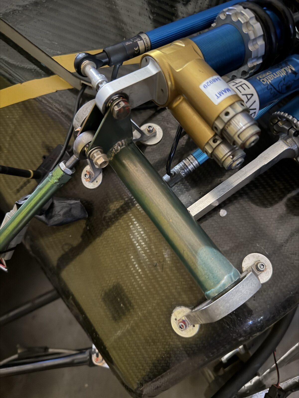
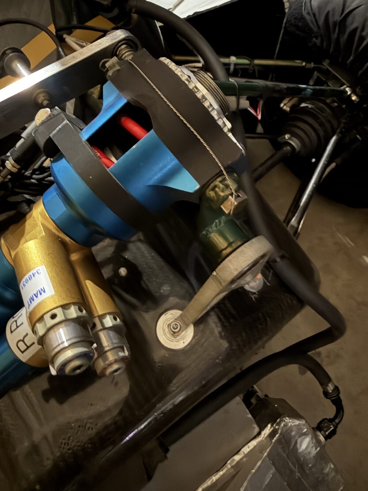
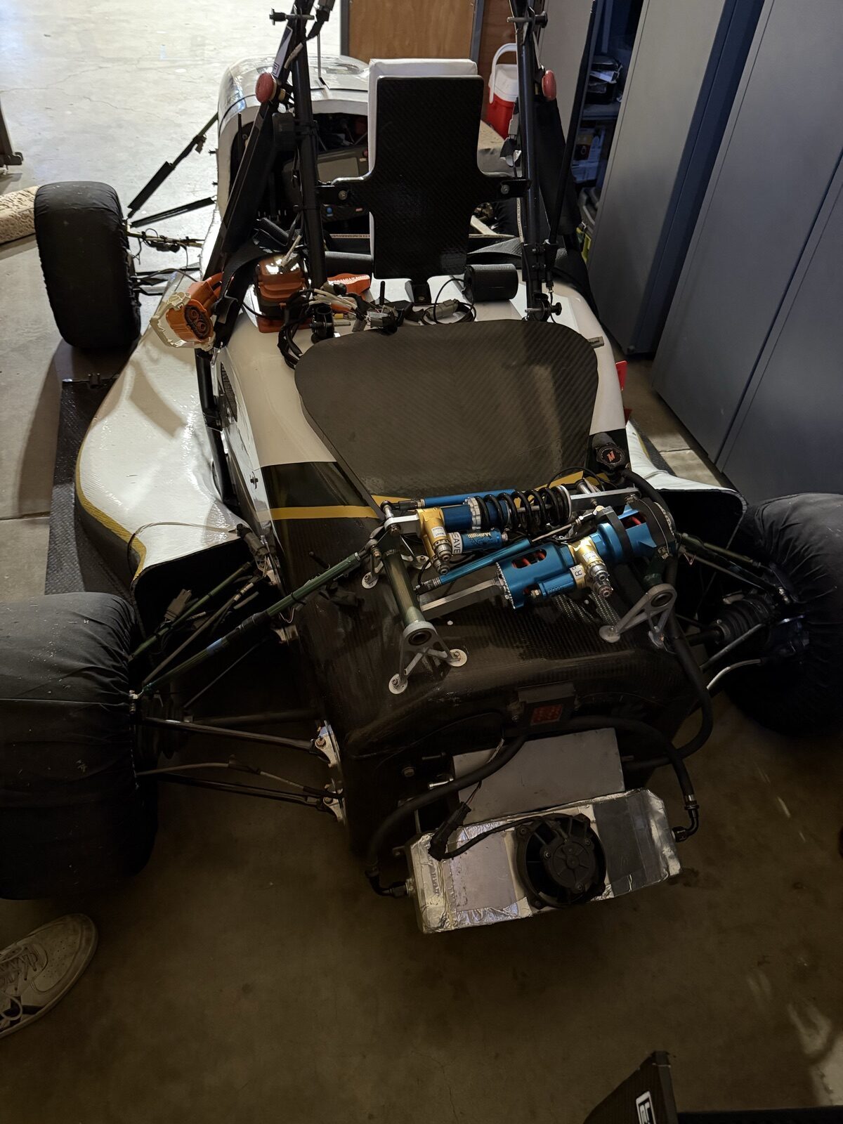
Justin's design separates the two. The pushrods from both wheels feed a shared rocker on the tub centerline, and the rocker geometry splits the wheel motion into two independent modes, each with its own Multimatic spring-damper. Heave and roll are tuned on their own terms — soft where the car needs grip over bumps, stiff where it needs to stay flat — with no anti-roll bar, two dampers per axle instead of two-plus-a-bar, and all of it mounted inboard where the mass belongs.

It is the same principle behind the "third spring" and interconnected suspensions used at the top of open-wheel racing, brought down to a student-built electric car — designed, machined, welded and bolted together by the suspension team, and run in anger at Formula SAE Electric 2026.

DETAIL A

WHY DECOUPLE

A race car's suspension is asked two contradictory questions. Over a bump, both wheels on an axle rise together and the car wants compliance — let the wheel follow the road so the tire keeps its load. In a corner, the outside wheel loads up while the inside unloads, the body tries to lean, and the car wants stiffness — keep the platform flat so the aero works and the tires stay at the camber they were designed for.

With one spring at each corner, both questions are answered by the same coil. Stiffen it for roll and the car skips over bumps; soften it for bumps and the car rolls onto its outside tires. The traditional fix is an anti-roll bar — a torsion bar that only acts when the two wheels move differently — but a bar adds roll stiffness without adding any roll damping, and it drags one wheel's bump input across to the other side of the car.

Decoupling the modes removes the compromise at the root. Heave gets a spring and a damper of its own; roll gets a spring and a damper of its own. Each can be changed at the track without touching the other.

DETAIL B

HOW THE ROCKER SPLITS THE MOTION

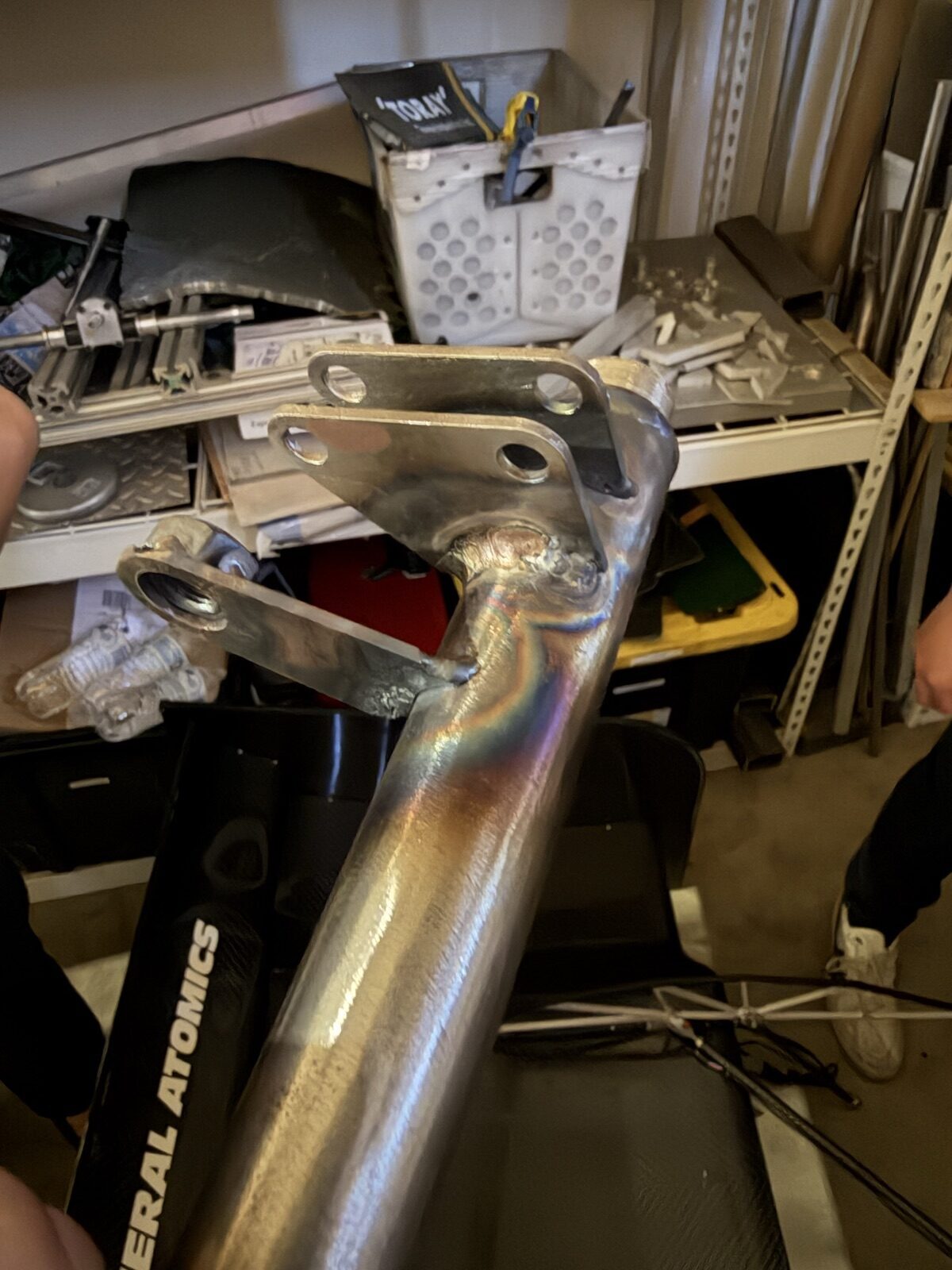
Each wheel drives a pushrod up into the tub. Instead of ending at its own damper, the two pushrods land on a shared rocker assembly mounted on the centerline — the welded pivot and machined arms in FIG. 04 and FIG. 05. The linkage is arranged so that when both pushrods move the same way, the heave damper compresses and the roll damper sees no net motion; when they move opposite ways, the roll damper works and the heave damper stays still.

Mechanically, the rocker is doing the sum and the difference of the two wheel travels. The lever ratios on each arm set the motion ratio for each mode — how much damper travel you get per millimetre of wheel travel — and those ratios are a design choice, not an accident of packaging. Getting them right, and keeping them close to linear through the whole travel, is most of the geometry work.

Because everything lives on the tub rather than out at the wheels, the dampers sit low and central, the unsprung mass at each corner is only the wishbones, pushrod, upright and wheel, and both units are reachable with the bodywork off for adjustment between runs.

DETAIL C

SCOPE OF WORK · SUSPENSION LEAD

  • C.1Owned the concept: made the case for a decoupled heave/roll layout over a conventional four-corner setup, and carried it from a sketch to hardware on the car.
  • C.2Designed the rocker geometry and mounting in CAD — pivot locations, arm lengths and motion ratios for each mode, packaged around the drivetrain and the carbon monocoque.
  • C.3Specified the two mode dampers and their springs, so heave and roll stiffness could be set independently rather than as a compromise.
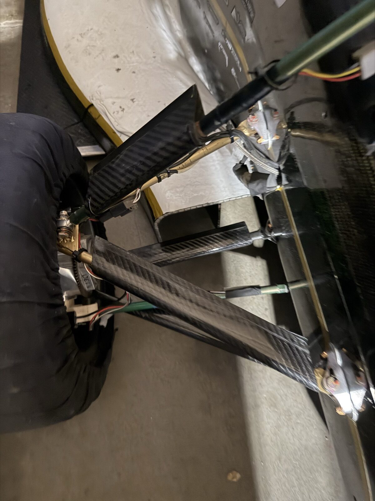
  • C.4Manufactured the parts: machined rocker arms and pickups on the mill and lathe, welded the steel rocker brackets and pivots, laid up and bonded the carbon-fibre wishbone ends.
  • C.5Assembled and set the corner-to-corner geometry on the car — pushrod lengths, toe links, ride height — and checked that heave and roll inputs really did separate as designed.
  • C.6Coordinated the suspension sub-team's schedule with chassis, drivetrain and aero so the rear assembly was on the car in time for testing and competition.
DETAIL D

MANUFACTURE + MATERIALS

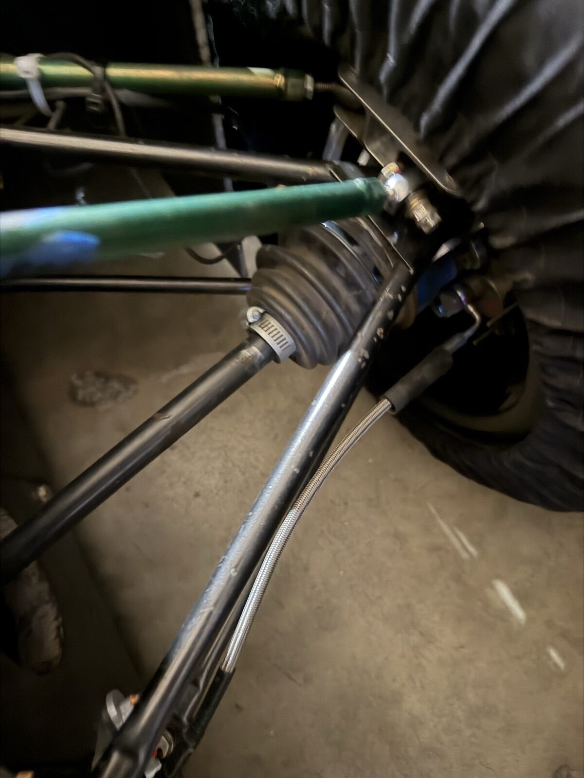
The photos show the mix of processes the assembly needed. The rocker pivots and pickup brackets are welded steel — the heat-tinted beads on the bracket in FIG. 06 are straight off the table, before finishing. The rocker arms and damper clevises are machined aluminium. The wishbones and pushrods are carbon-fibre tube with bonded metal ends (FIG. 08), which keeps the unsprung mass down where it matters most. The dampers themselves are Multimatic units, each labelled for its mode so nobody on the team plumbs a heave damper into the roll position at 2 a.m. before a test day.

Everything mounts to the carbon monocoque through bonded inserts and machined brackets — the loads from both rear wheels now arrive at a handful of points on the centerline, so those mounts were designed for the combined load rather than a single corner's.

DETAIL E

TUNING AT THE TRACK

The payoff is in how the car is set up. If the driver reports the car skating over a bumpy braking zone, the heave spring or heave damping comes down — and the roll stiffness in the corners is untouched. If the car leans too much through a slalom, the roll spring goes up — and the ride over bumps stays exactly as it was. On a conventional car each of those changes would have side effects on the other; here they are two separate knobs.

The honest trade-off is that there is no third, independent "single-wheel" mode. A bump under one wheel is, to the rocker, half heave and half roll, so both dampers respond. The geometry and the two rates have to be chosen together with that in mind, which is exactly the kind of coupled design problem the layout was chosen to teach.

Captions and part names are from the photographs; setup numbers — spring rates, motion ratios, damper clicks — are the team's and are not published here.

04 /

BILL OF MATERIALS

ITEM
DESCRIPTION
CATEGORY
STATUS
001
Mechanical Engineering
DOMAIN
OPERATIONAL
002
Suspension Design
VEHICLE DYNAMICS
OPERATIONAL
003
Vehicle Dynamics
ANALYSIS
OPERATIONAL
004
Engineering Drawings
DOCUMENTATION
OPERATIONAL
005
CNC Machining
MANUFACTURING
OPERATIONAL
END OF LIST · 05 ITEMS VERIFIED · LINKEDIN
05 /

MATRICULATION RECORD

UNIVERSITY · CALIFORNIA · PUBLIC

California Polytechnic State University

San Luis Obispo, California

PROGRAM B.S. Mechanical Engineering
CLASS STANDING Junior
FOCUS Vehicle Systems · Suspension
AFFILIATION Cal Poly Racing · FSAE
06 /

HAILING FREQUENCIES

STATUS · OPEN TO WORK RECRUITERS  ·  ON-SITE / HYBRID  ·  ALHAMBRA, CA + 3 MORE